

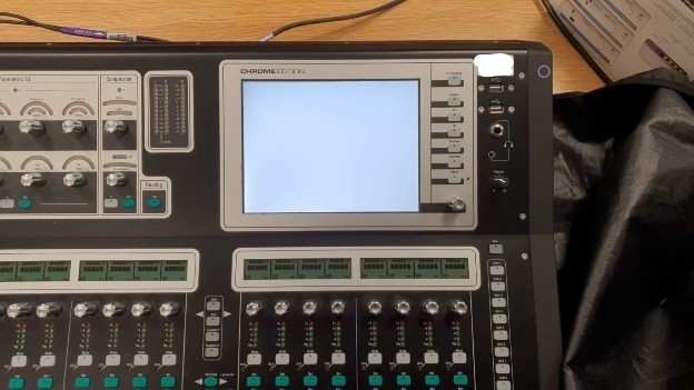
I have put together this guide on repairing the Alen and Heath GLD white screen of death which is becoming an increasingly common fault on these desks as they age. I do not recommend that you undertake this repair if you do not have a basic understanding of electronics, PC components and a good tool kit!
Disclaimer: Any repair you undertake yourself will void your warranty, if your desk is in warranty, send it away to be fixed. You undertake this repair at your own risk, I am not responsible for any damage, losses or injuries that may incur because of following this guide.
What causes the ‘white screen of death?
From my research into this problem through the GLD Users Facebook Group and Allen & Heath Community forum, the white screen of death appears to be caused by a failure of the SBC (Single-Board Computer) within the GLD desk. This is basically the brain of the desk, it holds the Linux operating system, it is the interface for the DSP boards, the control boards and the touchscreen display. The GLD uses a Fujitsu AMD ITX Industrial Motherboard, specifically the Fujitsu D3313-S13. The CR2032 CMOS battery on these motherboards has an expected lifetime of around 5 years. When this battery fails, the desk refuses to boot. The desk fails to boot because the SBC checks the status of this battery when it first powers on. If the battery is not outputting sufficient voltage, the board will not boot. The failure of the desk to boot when this battery gets low is in my opinion a design fault with GLD.
Why not just send the desk back to A&H?
By all means, you can, A&H have great support. But, if you haven’t got the time to send the desk away to be repaired, this will hopefully help.
Changing the battery
Replacing the battery may well fix your GLD, but it’s not quite as simple as that!
To replace the battery, you’re going to need your TORX bits. The chassis of the GLD is simple to open, flip the desk upside down and remove the bolts. For this fix, you may be able to remove just the top section of the desk – this is the section with the PSU and IO ports. However, I would recommend you also remove the bottom section as this makes it easier to work on the board, without risking damage to the internal wiring.
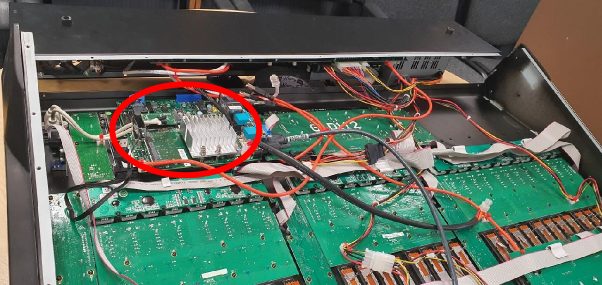
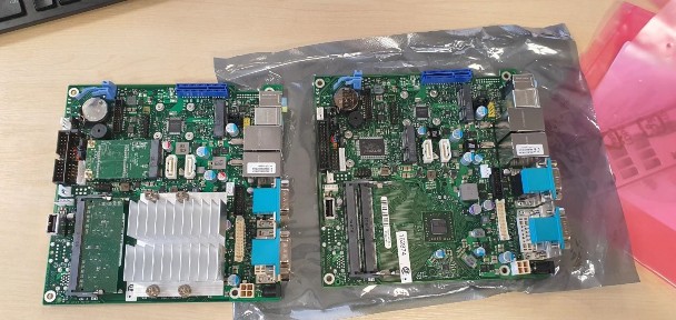
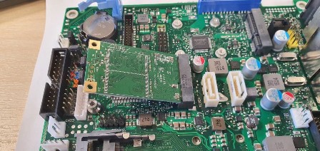
Once in, you will need to identify the SBC, it is the board with the big heatsink, that the USB, ethernet and serial cable connect to.
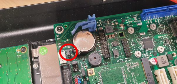
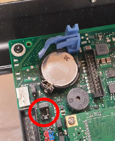
In the top left of this board, you will find the CR2032 CMOS battery, replace the battery with a new one. Now, you might think that this is all you need to do, but it is not. That boot check of the battery that I mentioned earlier, changing the battery still doesn’t allow the SBC to boot. To rectify this, you need to set the SBC into ALWON mode, using the ALWON jumper.
This appears to be the fix for the vast majority of GLD White Screen of Death cases. You should be able to power on the desk, and the desk boot normally.
What if my desk doesn’t boot?
If your desk didn’t boot, then you’re probably feeling a little bit disgruntled.
At this point, grab a PC monitor and a USB keyboard and follow these steps:
- Connect the monitor to the DVI port on the SBC.
- Connect the USB keyboard to the spare USB port on the SBC.
- Power on the desk
- Do you have a picture on the external monitor? If yes, carry on with this list. If no, skip ahead to the bios recovery section.
- If you have a picture, when the fujitsu logo appears, press F2 on the keyboard to open the BIOS. What has likely happened here is the CMOS battery has dropped so low, it has reset the CMOS memory and the BIOS settings. We need to configure the settings for the GLD’s touch screen display – skip ahead to ‘Configuring the LVDS’.
BIOS Recovery
If you don’t have a picture on the external monitor, it may be that the BIOS has become corrupted as a result of the CMOS memory losing power. We can attempt to recover the BIOS by downloading the BIOS from Fujitsu’s website. At this stage, recovering the BIOS is the best-case scenario, it may be that your GLD’s SBC board is dead and beyond recovery – but this is worth a try before you have to get your wallet out! To recover the BIOS, you’re going to need a blank USB stick and some patience.
- Download the latest bios from Fujitsu: https://support.ts.fujitsu.com/IndexDownload.asp?lng=en
You will need to search Fujitsu download site for the D3313-S13. This needs to be the download titled admin pack. The other download option is windows, and your GLD does NOT run on Windows.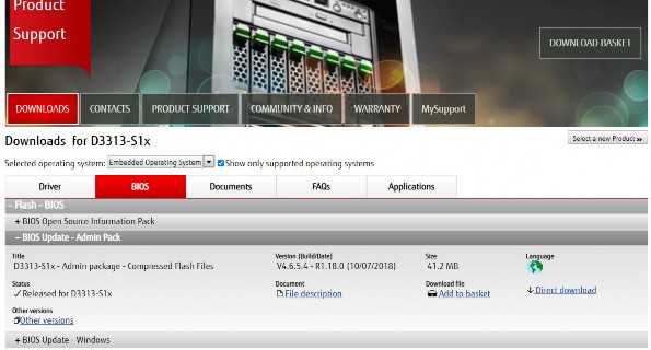
- Format the USB stick as a DOS bootable disk, if you’re not sure how to do this, download RUFUS, and use RUFUS to format the USB.
- Copy the .ROM bios file into the root of the freshly formatted USB memory stick.
- Make sure the desk is powered off.
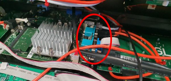
- Set the SBC into BIOS recovery mode by putting BIOS control jumper into RECOVERY mode as per the picture below.
- Disconnect all of the GLD’s USB connected DSP Boards and control surfaces from the SBC.
- Disconnect the Serial cable
- Insert the USB memory stick into the SBC.
- Power on the desk, if the SBC is functional it will recover the BIOS from the USB memory stick.
- Wait 5 minutes.
- Remove the USB stick
- Reset the BIOS Recovery jumper back into its normal position.
- Power on the desk – If you see the fujitsu logo appear on your external monitor, hit F2 to enter the bios configuration menu and skip ahead to ‘configuring the LVDS’
Don’t give up
At this point, if you are not seeing an output on the external display, I am sorry to tell you, but your SBC board is dead. If you want to use your desk again, you are going to have to get your wallet out, but try and remember all of the good times that you have had together.
It is at this point where I thought I had wasted enough time trying to fix it, I will send it off to Alen & Heath for repair. I opened a ticket and was referred to their UK service centre. When speaking with the service engineer, I explained what the issue was, and what I had tried so far to fix the SBC, they agreed that the SBC was dead and that it would need to be replaced.
For the SBC, the UK Service Centre quoted £850 EXVAT + £100 labor to replace the SBC + Postage. Total repair cost, roughly £1,000. This, in my opinion, is pretty steep for what is basically an ITX motherboard with an surface mounted AMD processor.
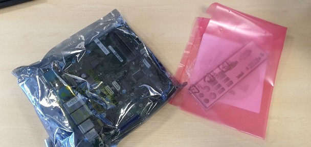
We already know the model number of the motherboard (D3313-S13), and we know that it is manufactured by Fujitsu. However, these are not a consumer part, they are an industrial motherboard for controlling industrial equipment. Trying to source one is not very easy, luckily, I’ve done it for you! I contacted many suppliers of embedded system components before I contacted Kontron in Germany. Kontron specialize in embedded computing technology and they can supply the D3313-S1 mITX.
Their UK distributor Rutronik24 had over 250+ in stock and I was able to order a replacement board that arrived within 48 hours, for a cost of £105. Yes, you read that right, £105.
https://www.rutronik24.co.uk/search-result/qs:d3313-s1/
When compared to the £850 that A&H wanted for the same component, this is a significant saving. Considering that this is a well-known cause of failure for the GLD series, I think A&H could do with reflecting on their pricing here.
Replacing the SBC
At this point, you are going to need your replacement board, TIM Clean, thermal grease, an antistatic wristband, a coffee, and some beers for later. I cannot stress the importance of using the antistatic wristband here – this is very sensitive electronics, you need to be well-grounded, any static could fry your components.
- Unplug any remaining daughter board connections to / from the SBC.
- Disconnect the power from the SBC board (4pin CPU Molex)
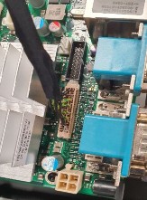
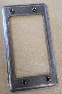
- Remove the LVDS display connection. Be careful when doing this, this connector is secured using glue. Carefully pick away the glue and remove the connector by pulling it up and away from the board.
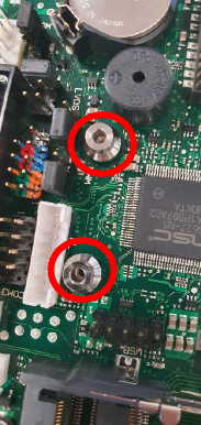
- Unscrew the 4x SBC mounting screws. Note: 2x of these screws are concealed by the cable tie mounting points, you’ll need to cut the cable ties and remove them to access the screw heads.
- Remove the SBC and place it next to the new board.
- On the new SBC, set the ALWON jumper to the enabled position.
- We now need to swap the Heatsink, RAM, and SSD onto the new SBC.
- Heatsink
- Unscrew the 4x Philips’s head bolts that hold the heatsink onto the old SBC.
- Lift the heatsink away, taking note of its orientation, it is asymmetrical.
- Remove the heatsink back plate, take note of its orientation, it is also asymmetrical.
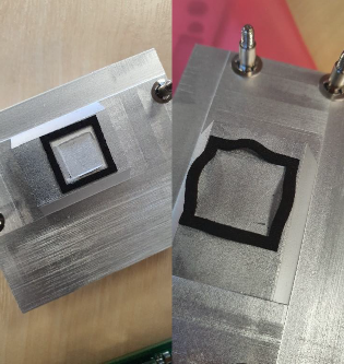
- Clean the old thermal grease away from the bottom of the heatsink using TIM Clean. If you’re not regularly dealing with thermal grease and heatsinks, I recommend you get some TIM Clean Wipes – they’re less messy and easier to use – but they don’t last as long as a bottle. You can the before and after shot of the cleaning below.
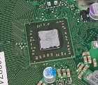
- Apply a very small amount of thermal grease directly to the CPU on the new SBC. When I say very small, I’m talking half the size of a grain of rice. Spread it around the CPU head using a plastic tool. I recommend the Noctua NT-H1 thermal paste.
- Install the CPU cooler backplate under the cooler.
- Carefully place the heatsink onto the CPU and tighten the screws. I recommend that you get each screw aligned with the backplate before then tightening in a diagonal pattern. Be very careful not to overtighten the heatsink. As soon as you feel resistance, stop.
- RAM
- Remove the RAM DIMM from the old SBC by carefully releasing the retaining clips – if you’re not sure how to do this, have a look on YouTube for a video on replacing laptop RAM.
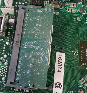
- Insert the RAM into the new SBC at 40 – 45 degree angle, be gentle with it – once the pins are no longer exposed, push down on the dam to secure it in the clips onto the board.
- Remove the RAM DIMM from the old SBC by carefully releasing the retaining clips – if you’re not sure how to do this, have a look on YouTube for a video on replacing laptop RAM.
- SSD
- Unscrew the two retaining bolts of the PCIE SSD on the old SBC.
- Remove the SSD and place on the antistatic matt.
- On the old SBC, remove the supporting feet that the SSD rested on – transfer to the new SBC.
- Gently insert the SSD into the port on the new SBC at a 40 – 45 degree angle. Once inserted, press the SSD down and secure it with the two bolts.
- Unscrew the two retaining bolts of the PCIE SSD on the old SBC.
- Heatsink
- Install the new SBC into the GLD chassis.
- Reconnect the LVDS cable to the new SBC.
- Reconnect the DSP and control surface USB daughter boards to the SBC.
- Reconnect the Serial connector
- Reconnect the Ethernet cable to the LAN port closest to the serial connector.
- Reconnect the USB Keyboard and external monitor from earlier.
- Reconnect the SBC Power connector (4-pin CPU)
- Carefully turn the GLD over so you can see the display.
Configuring the BIOS and LVDS (Low-voltage differential signaling) settings.
The good news, that’s the hard part done.
- Power on the GLD
- On the external monitor you should see the Fujitsu Boot Logo
- Press F2 to enter the BIOS.
- Navigated to Advanced and select the LVDS menu.
- Input the following settings:
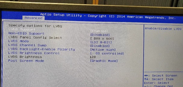
- Save and exit out of the BIOS.
At this point, you should now have working display on the GLD. The desk will continue to boot but it will take a while. You may have a cursor in the top left of the display, please be patient – we will fix this shortly.
Backup and wipe
- At this stage after a long wait, you should be back in the GLD OS, at this stage, if you have files saved on the console that you wish to recover – back them up to a USB stick.
- We now need to rebuilt the OS on the GLD, it’s had a hardware change it will be a little bit upset and running filesystem checks on every boot – hence why it took along time to boot on.
- Power down the GLD without shutting down the desk
- On boot you should be greeted with the error message stating that you did not correctly shut down.
- Select advanced on the menu.
- Select the option that says Reset OS
- Upon rebuild of OS, the GLD should boot much quicker.
- Install the latest firmware.
- Reboot the GLD.
Test, Test, Test
Before disconnecting the external monitor and USB keyboard, check that every function of the GLD is working correctly:
- Check each encoder is operating correctly.
- Check each fader is operating correctly.
- Check each button is operating correctly.
- Check the display of each channel’s LCD screen.
- Check that you can change the colour of each LCD screens.
- Check that you can connect the device via Ethernet.
- Check that the audio inputs and outputs are working as expected.
- Check the D-Snake and Expander connections function as expected.
If you’re happy that your GLD is back in action, disconnect the external display, disconnect the USB keyboard, and close her up.
If you have found this guide useful, please leave a comment below. If I have just saved you from a hefty repair bill, make a donation to a worthy charity.